
Installation and Use Manual 17
Installation and Setup
ProLink II Setup Transmitter StartupUsing ProLink IIBefore You Begin
Method 4: HART/Bell 202 temporary or hard-wired connection to Model 1700/2700 IS transmitters
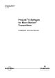
Using a VIATOR HART Interface, the PC can be connected directly to a transmitter’s primary mA
output terminals, to the output wires from these terminals, or to any point in a multidrop network that
is wired to these terminals. Figure 2-4 shows the wiring for this connection type.
1. At the PC, connect the VIATOR HART Interface to the PC’s serial or USB port.
2. Attach the VIATOR HART Interface leads:
• To any point on the network (hard-wired connection)
• Directly to the primary mA output terminals on your transmitter (temporary connection).
See Table 2-8
• To the output wires from the primary mA output terminals on your transmitter (hard-wired
connection). See Table 2-8
The connection is polarity-insensitive; you can attach either lead to either terminal. For
assistance in identifying the primary mA output terminals, see Appendix A.
3. Ensure that your wiring meets the following requirements:
• For basic analog output operation, the primary mA output requires an external power
supply with a minimum of 250 Ω and 17.5 volts. See Figure 2-5.
• For communication, the VIATOR HART Interface must be connected across a resistance
of 250–600 Ω. See Figure 2-4.
To meet the resistance requirements, you may use any combination of resistors R1, R2,
and R3:
- If no other device is connected to the primary mA output, add resistor R1 in series with the
primary mA output.
- If the primary mA output is connected to a remote device such as a DCS or a PLC with an
internal resistor (R2), ensure its value is between 250 and 600 Ω. If it is lower than 250 Ω,
add resistor R1 to the connection so that the overall resistance (R1 + R2) is between 250
and 600 Ω.
- If your DCS or PLC does not have an internal resistor, add resistor R3 and make sure its
value is between 250 and 600 Ω
.
Table 2-8 Primary mA output terminals – Method 4
Transmitter
Terminals
PV + PV –
Model 1700/2700 IS 1 2


 England
  Deutschland
  France
  Italia
  Polska
  United Kingdom
  Россия
  Nederland
  España
  Magyarország
  Sverige
  România
  Portugal
  Colombia
  Suomi
Suomi  New Zealand
  Česká republika
  Türkiye
  Danmark
  日本
日本