
Control circuit
INSTALLATION AND WIRING
37
2
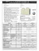
2.6.2 Details on the control circuit terminals of the
converter unit (FR-CC2)
The input signal function of the terminals in can be selected by setting Pr.178, Pr.187, Pr.189 to Pr.195 (I/O terminal
function selection).
For the parameter details, refer to the FR-CC2 Instruction Manual.
Input signal
Type
Terminal
Symbol
Terminal name Terminal function description Rate Specification
Contact input
RES Reset
Use this signal to reset a fault output provided when a protective function
is activated. Turn ON the RES signal for 0.1 s or longer, then turn it OFF.
In the initial setting, reset is always enabled. By setting Pr.75, reset can
be set enabled only at fault occurrence of the converter unit. The inverter
recovers about 1s after the reset is released.
Input resistance
4.7 k
Voltage when
contacts are open: 21
to 27 VDC
When contacts are
short-circuited: 4 to 6
mADC
OH
External thermal
relay input
The external thermal relay input (OH) signal is used when using an
external thermal relay or a thermal protector built into the motor to
protect the motor from overheating.
When the thermal relay is activated, the inverter trips by the external
thermal relay operation (E.OHT).
RDI Contact input The function can be assigned by setting Pr.178.
SD
Contact input
common (sink)
Common terminal for contact input terminal (sink logic) and terminal FM
———
External transistor
common (source)
Connect this terminal to the power supply common terminal of a
transistor output (open collector output) device, such as a programmable
controller, in the source logic to avoid malfunction by undesirable
current.
24 VDC power supply
common
Common terminal for the 24 VDC power supply (terminal PC, terminal
+24)
Isolated from terminals 5 and SE.
PC
External transistor
common (sink)
Connect this terminal to the power supply common terminal of a
transistor output (open collector output) device, such as a programmable
controller, in the source logic to avoid malfunction by undesirable
current.
Power supply voltage
range 19.2 to 28.8
VDC
Permissible load
current 100 mA
Contact input
common (source)
Common terminal for contact input terminal (source logic).
24 VDC power supply
common
Can be used as a 24 VDC 0.1 A power supply.
Power supply input
+24
24 V external power
supply input
For connecting a 24 V external power supply.
If a 24 V external power supply is connected, power is supplied to the
control circuit while the main power circuit is OFF.
Input voltage 23 to
25.5 VDC
Input current 1.4 A or
less


 England
  Deutschland
  France
  Italia
  Polska
  United Kingdom
  Россия
  Nederland
  España
  Magyarország
  Sverige
  România
  Portugal
  Colombia
  Suomi
Suomi  New Zealand
  Česká republika
  Türkiye
  Danmark
  日本
日本