
Electro-magnetic interference (EMI) and leakage currents
64
PRECAUTIONS FOR USE OF THE INVERTER
Data line filter
Data line filter is effective as an EMI countermeasure. Provide a data line filter for the detector cable, etc.
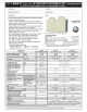
<Example> Data line filter: ZCAT3035-1330 (by TDK)
ESD-SR-250 (by NEC TOKIN)
Impedance (ZCAT3035-1330)
The impedance values above are reference values, and not
guaranteed values.
Noise
propagation path
Countermeasure
(a)(b)(c)
When devices that handle low-level signals and are liable to malfunction due to electromagnetic noises, e.g.
instruments, receivers and sensors, are contained in the enclosure that contains the inverter or the converter unit,
or when their signal cables are run near the inverter, the devices may malfunction due to by air-propagated
electromagnetic noises. The following countermeasures must be taken:
• Install easily affected devices as far away as possible from the inverter or the converter unit.
• Run easily affected signal cables as far away as possible from the inverter or the converter unit, and its I/O
cables.
• Do not run the signal cables and power cables (inverter or converter unit I/O cables) in parallel with each other
and do not bundle them.
• Set the EMC filter ON/OFF connector of the converter unit to the ON position. (Refer to page 66.)
• Inserting a line noise filter into the output suppresses the radiated noise from the cables.
• Use shielded cables as signal cables and power cables and run them in individual metal conduits to produce
further effects.
(d)(e)(f)
When the signal cables are run in parallel with or bundled with the power cables, magnetic and static induction
noises may be propagated to the signal cables to cause malfunction of the devices and the following
countermeasures must be taken:
• Install easily affected devices as far away as possible from the inverter or the converter unit.
• Run easily affected signal cables as far away as possible from the inverter or the converter unit, and its I/O
cables.
• Do not run the signal cables and power cables (inverter or converter unit I/O cables) in parallel with each other
and do not bundle them.
• Use shielded cables as signal cables and power cables and run them in individual metal conduits to produce
further effects.
(g)
When the power supplies of the peripheral devices are connected to the power supply of the inverter or the
converter unit in the same line, its generated noises may flow back through the power supply cables to cause
malfunction of the devices and the following countermeasures must be taken:
• Set the EMC filter ON/OFF connector of the converter unit to the ON position. (Refer to page 66.)
• Install the line noise filter to the power cables (output cables) of the inverter.
(h)
When a closed loop circuit is formed by connecting the peripheral device wiring to the inverter or the converter unit,
leakage currents may flow through the earthing (grounding) cable of the inverter or the converter unit to cause the
device to malfunction. In that case, disconnecting the earthing (grounding) cable from the device may stop the
malfunction of the device.
Impedance ()
10 to 100 MHz 100 to 500 MHz
80 150
34 1
TDK
39 1
Product name Lot number
30 1
Cable fixing
band mount
13 1
OUTLINE DIMENSION DRAWINGS (ZCAT3035-1330)
[Unit: mm]


 England
  Deutschland
  France
  Italia
  Polska
  United Kingdom
  Россия
  Nederland
  España
  Magyarország
  Sverige
  România
  Portugal
  Colombia
  Suomi
Suomi  New Zealand
  Česká republika
  Türkiye
  Danmark
  日本
日本