
Power supply harmonics
PRECAUTIONS FOR USE OF THE INVERTER
67
3
3.2 Power supply harmonics
3.2.1 Power supply harmonics
The inverter may generate power supply harmonics from its converter circuit to affect the power generator, power factor
correction capacitor etc. Power supply harmonics are different from noise and leakage currents in source, frequency band and
transmission path. Take the following countermeasure suppression techniques.
• The differences between harmonics and noises
• Countermeasures
• The power factor improving capacitor and surge suppressor on the inverter output side may be overheated or damaged by
the harmonic components of the inverter output. Also, since an excessive current flows in the inverter to activate overcurrent
protection, do not provide a capacitor and surge suppressor on the inverter output side when the motor is driven by the
inverter. For power factor improvement, install a reactor on the inverter input side or in the DC circuit.
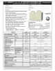
Item Harmonics Noise
Frequency
Normally 40th to 50th degrees or less (3 kHz
or less).
High frequency (several 10 kHz to 1 GHz order).
Environment To-electric channel, power impedance. To-space, distance, wiring path,
Quantitative understanding Theoretical calculation possible. Random occurrence, quantitative grasping difficult.
Generated amount Nearly proportional to the load capacity.
Changes with the current variation ratio. (Gets larger as
switching speed increases.)
Affected equipment immunity Specified by standards per equipment. Different depending on maker's equipment specifications.
Countermeasure Provide a reactor. Increase distance.
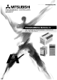
The harmonic current generated from the inverter
to the input side differs according to various
conditions such as the wiring impedance, whether
a reactor is used or not, and output frequency and
output current on the load side.
For the output frequency and output current, we
understand that this should be calculated in the
conditions under the rated load at the maximum
operating frequency.
The converter unit (FR-CC2) is equipped with the DC reactor.
DC reactor
∗1
Inverter/
converter
R
S
TZ
Y
X
U
V
W
R/L1
S/L2
T/L3
M
AC reactor
(FR-HAL)
Do not insert power
factor improving capacitor.
MCCB MC
Power supply


 England
  Deutschland
  France
  Italia
  Polska
  United Kingdom
  Россия
  Nederland
  España
  Magyarország
  Sverige
  România
  Portugal
  Colombia
  Suomi
Suomi  New Zealand
  Česká republika
  Türkiye
  Danmark
  日本
日本