
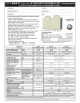
Measurement of main circuit voltages, currents and powers
PRECAUTIONS FOR MAINTENANCE AND INSPECTION
93
5
Measuring points and instruments
Item Measuring point Measuring instrument Remarks (reference measured value)
Converter unit (FR-CC2)
Power supply
voltage
V
1
Across R/L1 and S/L2,
S/L2 and T/L3,
T/L3 and R/L1
Moving-iron type AC voltmeter
Commercial power supply
Within permissible AC voltage fluctuation (Refer
to page 98.)
Power supply side
current
I
1
R/L1, S/L2, T/L3 line
current
Moving-iron type AC ammeter
Power supply side
power
P
1
R/L1, S/L2, T/L3 and
Across R/L1 and S/L2,
S/L2 and T/L3,
T/L3 and R/L1
Digital power meter (for inverter) or
electrodynamic type single-phase
wattmeter
P
1 = W11 + W12 + W13 (3-wattmeter method)
Power supply side
power factor
Pf
1
Calculate after measuring power supply voltage, power supply side current and power supply side power.
Converter output Across P/+ and N/-
Moving-coil type
(such as tester)
Inverter LED is lit. 1.35 V
1
Operation enable
signal
External thermal
relay signal
Reset signal
Across RDI, OH,
RES(+) and SD (for
sink logic)
Moving-coil type
(tester and such may be used.)
(internal resistance 50 k or more)
When open
20 to 30 VDC
ON voltage: 1 V or less
"SD" is
common
Alarm signal
Across A1 and C1
Across B1 and C1
Moving-coil type
(such as tester)
Continuity check
[Normal] [Fault]
Across A1 and C1 Discontinuity Continuity
Across B1 and C1 Continuity Discontinuity
Inverter
Output side
voltage
V
2
Across U and V, V and
W, and W and U
Rectifier type AC voltage meter
(moving-iron type cannot
measure.)
Difference between the phases is within 1% of
the maximum output voltage.
Output side
current
I
2
U, V and W line
currents
Moving-iron type AC ammeter
Difference between the phases is 10% or lower
of the rated inverter current.
Output side power
P
2
U, V, W and
across U and V, V and
W
Digital power meter (for inverter) or
electrodynamic type single-phase
wattmeter
P
2 = W21 + W22
2-wattmeter method (or 3-wattmeter method)
Output side power
factor
Pf
2
Calculate in similar manner to power supply side power factor.
Frequency setting
signal
Across 2, 4(+) and 5
Moving-coil type
(tester and such may be used.)
(internal resistance 50 k or more)
0 to 10 VDC, 4 to 20 mA
"5" is .
common
Across 1(+) and 5 0 to 5 VDC and 0 to 10 VDC
Frequency setting
power supply
Across 10(+) and 5 5.2 VDC
Across 10E(+) and 5 10 VDC
Frequency meter
signal
Across AM(+) and 5
Approximately 10 VDC at maximum
frequency
(without frequency meter)
Across CA(+) and 5
Approximately 20 mADC at
maximum frequency
Across FM(+) and SD
Approximately 5 VDC at maximum
frequency
(without frequency meter)
Pulse width T1: Adjust with C0
(Pr.900).
Pulse cycle T2: Set with Pr.55.
(frequency monitor only)
"SD" is
common
Start signal
Select signal
Reset signal
Output stop signal
Across STF, STR, RH,
RM, RL, JOG, RT, AU,
STOP, CS, RES,
MRS(+) and SD (for
sink logic)
When open
20 to 30 VDC
ON voltage: 1 V or less
Fault signal
Across A1 and C1
Across B1 and C1
Moving-coil type
(such as tester)
Continuity check
[Normal] [Fault]
Across A1 and C1 Discontinuity Continuity
Across B1 and C1 Continuity Discontinuity
Pf1
P1
3V1 I 1
------------------------
100=
%
Pf2
P2
3V2 I2
------------------------
100=
%
8VDC
T1


 England
  Deutschland
  France
  Italia
  Polska
  United Kingdom
  Россия
  Nederland
  España
  Magyarország
  Sverige
  România
  Portugal
  Colombia
  Suomi
Suomi  New Zealand
  Česká republika
  Türkiye
  Danmark
  日本
日本